Offshore Wind Power Foundation: How to Select the Most Reliable MV Cables for Complex Environments
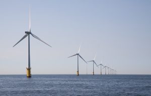
As the global energy transition accelerates, offshore wind farms are evolving comprehensively towards deep-sea locations and large-capacity installations. In this vast industrial chain, Medium Voltage (MV) Collection Cables play the role of the “aorta,” connecting wind turbines to substations.
The coastal environment is extremely complex, with sea wind intensities varying across different regions; taking several of China’s maritime zones as examples, the magnitude of wind forces to which they are subjected differs significantly from one another.
| Environmental Parameter | Unit | Bohai Sea | Yellow Sea | East China Sea | South China Sea |
| Climate Conditions | |||||
| Annual Minimum Air Temperature | ℃ | -20 | -20 | -10 | 5 |
| Annual Maximum Air Temperature | ℃ | 35 | 35 | 35 | 40 |
| Max Temperature at Relative Humidity (≥95%) | ℃ | 25 | 25 | 28 | 28 |
| Solar Irradiance | W/m² | 1000 | 1000 | 1120 | 1120 |
| Icing and Frosting Conditions | – | Yes | Yes | Yes | No |
| Hydrological Conditions | |||||
| Sea Surface Temperature Range | ℃ | -3 ~ 30 | -3 ~ 30 | 3 ~ 30 | 10 ~ 35 |
| Maximum Tidal Range | m | 5 | 7 | 9 | 7 |
| Maximum Wave Height | m | 11 | 11 | 15 | 20 |
| Sea Surface Current Velocity | m/s | 0.6 | 3 | 3 | 3 |
| Floating Ice Thickness | m | 0.3 | — | — | — |
| Chemical Conditions | |||||
| Salinity in Seawater | % | 3.1 ~ 3.4 | 3.15 ~ 3.25 | 3.3 ~ 3.4 | 3.3 ~ 3.4 |
In these sea areas, wind speeds vary significantly under extreme weather conditions, thus placing higher demands on the quality of cables.
| Category | Item/Standard | Details/Value |
| IEC Wind Turbine Class Standards | Class I Turbines | Maximum design limit wind speed: 50 m/s |
| IEC Wind Turbine Class Standards | Class II Turbines | Maximum design limit wind speed: 42.5 m/s |
| IEC Wind Turbine Class Standards | Class III Turbines | Maximum design limit wind speed: 37.5 m/s |
| Regional Design Differences | South China Sea | Characterized by ‘high wind – moderate waves’. 50-year extreme wind speed: 42 m/s. Focus on stability against typhoons. |
| Regional Design Differences | Other Areas (e.g., South Africa) | Characterized by ‘moderate wind – giant waves’. 50-year extreme wave height: 14 m. Focus on preventing resonance failure. |
| Actual Project Reference | Xuwen Offshore Wind Farm (Guangdong) | Hub height (140m) 50-year extreme wind speed design value: 78.82 m/s. Indicates need for higher safety redundancy in typhoon-prone areas. |
However, facing extreme environments characterized by high salt spray, strong ocean currents, and complex mechanical stresses, how do we select the right cables? This guide provides an in-depth analysis from three dimensions: technical selection, materials science, and international standards.
Environmental Definition: The “Three Major Tests” for Cable Selection
Before entering parameter screening, it is crucial to clarify the harsh requirements the offshore wind environment places on cables:
Dynamic Fatigue
Cables inside floating wind turbines or towers must withstand dynamic bending caused by waves and wind over the long term. For example, models like FDEF, FDEU, FDEH, and H07BN4-F utilize Class 5 or Class 6 flexible copper conductors, stranded from extremely fine copper wires, ensuring the cable can withstand large-angle torsion without breaking. The main materials used are Ethylene Propylene Rubber (EPR) or Silicone Rubber, capable of withstanding long-term operating temperatures of 90°C and short-circuit temperatures up to 250°C.
Chloroprene Rubber (CR): Offers excellent oil resistance, weather resistance, and flame retardancy.
Thermoplastic Polyurethane (TPU): Takes performance to the next level with exceptional tensile strength, toughness, and aging resistance. It maintains flexibility even in extreme cold, overcoming the drawbacks of ordinary rubber.
Torsion Resistance: Extremely strong. For instance, H07BN4-F cables can withstand over 3,600 cycles of positive and negative rotation of 1080° (3 turns) at room temperature (10m sample) without sheath cracking. Some high-end aluminum core torsion-resistant cables have even passed torsion tests exceeding 50,000 cycles.
Low-Temperature Performance: Typically required to adapt to -40°C environments, with severe cold types reaching -55°C, ensuring operation in frigid regions.
Floating Wind Turbines: These do not have fixed foundations on the seabed and sway with wind and waves. Therefore, the “Dynamic Submarine Cable” connecting the turbine to the static seabed cable—lacking a unified model code like tower cables—is highly customized, often exceeding 35kV as the channel for power transmission.
Water Treeing
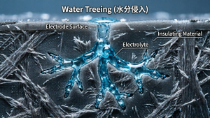
Cable insulation and sheathing are not absolutely impermeable; microscopic voids exist within the polymer molecules. When cable ends are poorly sealed, the outer sheath is damaged, or the cable is in a waterlogged environment for long periods, external water molecules slowly penetrate the interior via diffusion driven by concentration gradients. This is the basic principle of permeation—water molecules migrate from high to low concentration areas until humidity equilibrium is reached.
However, the real destruction occurs after moisture enters. When the cable is energized, a strong electric field exists within the insulation. Under the influence of this field, trace amounts of infiltrated water gradually form dendritic microscopic water-filled channels starting from impurities, micropores, air gaps, and uneven areas at the interface between the insulation and the semi-conductive layer. This is the phenomenon of Water Tree Aging.
Water trees range from 0.1 microns to a few microns in diameter, spreading through the insulation like capillaries. Higher humidity, temperature, voltage, and ion content in the water all accelerate the development of water trees.
The hazard of water trees lies in their irreversible accumulation. As they gradually penetrate the insulation, the dielectric strength of materials like Cross-linked Polyethylene (XLPE) continuously drops, partial discharge intensifies, and eventually leads to insulation breakdown and total cable scrapped.. This process usually takes over 8 years but accelerates significantly under harsh conditions. Therefore, the core logic of cable waterproofing has only two paths:
One: Prevent water from entering.
Two: Block longitudinal propagation after water enters.
Generally, waterproof cables are used for this situation. However, “waterproof cables” are not a single type but a multi-level product system ranging from “moisture resistant” to “submerged long-term operation” based on application severity.
- JHS/JHSB – Specialized Waterproof Rubber Sheathed Cables for Underwater Operations
JHS is the most widely used general waterproof cable model, designed for submersible motors, pumps, and underwater lighting.
JHS Type: Rated voltage 300/500V, long-term allowable operating temperature not exceeding 65°C.
JHSB Type: Rated voltage 6kV, used for drainage submersible pumps, long-term allowable operating temperature up to 85°C.
- YJV22 / VV22 – Moisture Resistance of Steel Tape Armored Power Cables
YJV22 (XLPE Insulation, Steel Tape Armor, PVC Outer Sheath) and VV22 (PVC Insulation, Steel Tape Armor, PVC Outer Sheath) are the most common armored cables in engineering. The “22” in the model indicates double steel tape armor plus PVC outer sheath. Their waterproofing logic differs from JHS, relying mainly on physical protection plus outer sheath moisture resistance. The steel tape armor provides powerful mechanical protection, effectively resisting external damage during laying and use, preventing scratches or crushing of the outer sheath, thereby indirectly protecting the inner insulation from moisture. The outer PVC sheath acts as a direct moisture barrier. It must be clarified that YJV22 is suitable for damp environments like direct burial or cable trenches but is not designed for long-term immersion. If the cable trench is waterlogged and the cable head sealing is poor, moisture can still enter from the ends or damaged spots.
Corrosion Risks
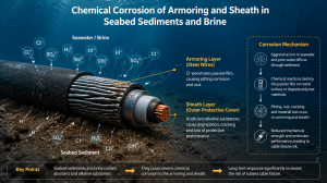
Seabed sediments and saltwater contain large amounts of acidic and alkaline substances that aggressively chemically erode armor layers and sheaths. Corrosion mainly occurs in five aspects:
Electrochemical Corrosion: Seawater has a salinity of about 3.5% and a chloride ion concentration as high as 19.35 g/L, acting as a natural strong electrolyte solution. When seawater contacts copper or aluminum conductors inside the cable, a galvanic cell effect forms between the metal and seawater, causing electrochemical reactions. The corrosion rate can be 5 to 8 times faster than in terrestrial environments. This is the most direct cause of failure for metal components in marine environments.
Chemical Degradation: Seawater is equally harsh on polymeric materials. At high temperatures, seawater catalyzes the hydrolysis of molecular chains in materials like polyesters and polyurethanes, causing the sheath to harden, crack, and insulation resistance to drop continuously. Meanwhile, dissolved oxygen and UV rays in seawater attack weak groups in polymer chains, triggering oxidative degradation, causing the sheath to powder, become brittle, and significantly lose tensile strength. Even chemically stable XLPE faces more tricky hidden dangers if the sheath is breached and seawater seeps in.
Microbiologically Influenced Corrosion (MIC): Marine organisms and sediments on the seabed produce corrosive substances like hydrogen sulfide and organic acids during metabolism. These substances accelerate the degradation of polyolefin materials, forming local pits on the sheath surface, opening breakthrough points for further seawater penetration.
Mechanical-Corrosion Synergistic Failure: Wave impact, vessel swaying, and current dragging cause repeated bending and vibration of cables. Sheaths are more susceptible to chloride ion penetration at stress concentration points, and cracks accelerate propagation under the dual action of corrosion and mechanical fatigue. Abrasion of submarine cables against reefs or squeezing of marine cables against pulleys causing sheath damage allows seawater to intrude directly, triggering chain corrosion reactions.
Water Tree Aging:
When the sheath is damaged and seawater seeps inside, under the electric field, moisture gradually forms dendritic microscopic water-filled channels (water trees) starting from impurities and micropores in the insulation. Once formed, water trees are irreversible; they spread through the insulation like capillaries, eventually leading to breakdown and total scrapped..
Facing the multi-faceted erosion of seawater, the defense system of seawater-resistant cables is constructed in layers, with each layer corresponding to a specific corrosion mechanism:
Layer 1: Conductor Protection – Active Isolation via Tinned Copper Wires
Conductors in seawater cables typically use stranded fine tinned copper wires. The tin plating serves a dual purpose: it prevents direct contact between the copper conductor and trace seawater that might seep in, fundamentally suppressing electrochemical corrosion; and it improves adhesion between the conductor and insulation, reducing interface defects. For higher requirements, high-purity low-oxygen copper with purity over 99.95% is used to reduce the risk of local galvanic corrosion caused by impurities from the material source.
Layer 2: Insulation Protection – Low Water Absorption Barrier of XLPE and EPR
The insulation layer is the core line of defense preventing seawater from contacting the conductor. Cross-linked Polyethylene (XLPE) has a volume resistivity exceeding 1×10¹⁷ Ω·cm, dielectric strength up to 40 kV/mm, and extremely low water absorption, making it the mainstream insulation material for submarine cables. Ethylene Propylene Rubber (EPR) also boasts excellent water resistance and electrical stability. The three-layer co-extrusion process forms the inner shield, insulation, and outer shield in one go, eliminating interlayer interface defects and significantly reducing the probability of water tree initiation.
Layer 3: Water-Blocking Structure – Dual Lockdown of Radial and Longitudinal
Water-blocking design has two dimensions. Radial water blocking relies on longitudinally wrapped aluminum-plastic composite tape. The metal aluminum layer is almost impermeable to water. Combined with water-swellable powder or tape, if trace moisture penetrates, the expanding material quickly fills all gaps, blocking the penetration path. Longitudinal water blocking fills conductor interstices with water-swellable yarn or compound and sets a hot-melt adhesive water-blocking core in the cable center to prevent water from migrating long distances along the cable length once it enters the end. Terminal sealing uses a triple structure of heat-shrink caps, epoxy resin potting, and stainless steel waterproof joints to seal the weakest end entry points.
Layer 4: Armor Protection – The Mechanical Shield of Steel Wire Armor
The steel wire armor layer is the cable’s “reinforced iron bone.” Double-layer reverse-laid galvanized steel wires, with inner and outer layers arranged at different lay angles, have a breaking force exceeding 1200 kN. They can withstand huge tensile forces during laying and operation, as well as resist seabed reef abrasion, fishing net dragging, and anchor impact. The coating system on the steel wire surface is typically an electro-galvanized base layer plus a zinc-aluminum alloy intermediate layer, covered with an epoxy resin coating, with corrosion area not exceeding 5% after 3000 hours of salt spray testing.
Layer 5: Outer Sheath – Material Choice Determines Life Limit
The outer sheath is the outermost line of defense against seawater erosion; material choice directly determines service life.
High-Density Polyethylene (HDPE): With tensile strength reaching 24 MPa, excellent seawater corrosion resistance, and mechanical protection, it is the classic sheath material for submarine cables, with a design life exceeding 30 years.
Thermoplastic Polyurethane (TPU): Represents a higher performance choice—its molecular chains form a dense hydrogen bond network with polar groups, resulting in a chloride ion permeability only one-tenth that of PVC. High-quality marine-grade TPU increases urea bond density and hard segment content, significantly boosting intermolecular forces. After soaking in 70°C seawater for 3000 hours, the retention rate of elongation at break remains over 85%. For dynamic applications like floating turbines and marine cables, TPU’s comprehensive advantages in hydrolysis resistance, salt spray resistance, and dynamic fatigue are particularly prominent.
In ultra-high voltage and deep-sea critical applications, there is the ultimate solution of Lead Alloy Sheathing. Lead-antimony alloy sheaths are continuously extruded to seamlessly wrap the cable core. In seawater, a dense lead oxide protective film 2-5 microns thick forms on the surface, with an annual corrosion rate below 0.03 mm and a design life exceeding 25 years.
- Core Technical Parameter Selection Recommendations
Conductor Material: The Trade-off between Performance and Cost
Copper: Possesses excellent conductivity and fatigue resistance. Copper core cables are the preferred choice inside turbine towers or in space-constrained narrow areas.
| Material Type | State | Conductivity (% IACS) | Resistivity (nΩ·m) |
| Pure Copper (ETP) | Annealed (Soft) | 100% ~ 101% | 17.24 |
| Pure Copper (ETP) | Hard-drawn (Cold-worked) | 97% ~ 98% | 17.8 |
| Oxygen-Free Copper (OFC) | Annealed | 100% ~ 102% | 17 |
| Copper-Silver Alloy | Hard-drawn | 90% ~ 95% | 18.5 |
| Copper-Magnesium Alloy | Hard-drawn | 80% ~ 85% | 20 |
Aluminum: The mainstream market choice for 2026. In long-distance seabed布线, aluminum core cables can reduce weight by approximately 30%-50%, significantly lowering installation vessel load requirements and total CAPEX.
Insulation Layer: Water Tree Resistance is Core
To combat the “Water Tree” phenomenon, TR-XLPE (Tree Retardant Cross-linked Polyethylene) insulation must be used. Its mechanism works in two steps:
Step 1: Neutralizing Harmful Ions. Trace moisture penetrating the insulation ionizes into charged ions under the electric field; these ions migrate directionally under the field’s drive, acting as “catalysts” for water tree growth. The water tree inhibitor in TR-XLPE is a polar additive that actively attracts and captures these ions, binding them near molecular chains and preventing free migration and aggregation.
Step 2: Reducing Local Electric Field Strength. Once harmful ions are neutralized by the inhibitor, the local high electric fields that would otherwise concentrate at impurities or defects are significantly weakened. Water tree initiation requires a sufficiently strong local electric field to drive directional water alignment and penetration; once the field strength drops, the water tree loses its driving force, making it difficult to initiate or grow rapidly.
In short, ordinary XLPE is “passive,” waiting for water trees to grow and cause problems; TR-XLPE is “active defense,” using chemical means to eliminate the conditions for water tree formation.
Industry Trend: From current practice, 66kV technology is showing significant advantages in pilot projects and new large-scale wind farms and is considered the future development direction.
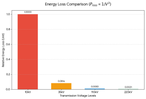
Core Principle of 66kV Technology: High Voltage for Loss Reduction
Imagine it as a highway. Current is like cars on the road, and voltage is like the speed of each car. Our goal is to transport a certain amount of cargo (i.e., transmit fixed electrical power).
Transmission Efficiency Formula
P = V × I | Ploss = I² × RThe biggest benefit of reducing current is a significant drop in energy loss. Since line loss is proportional to the square of the current, high-voltage transmission is the key to minimizing wasted electrical energy.
66kV technology cleverly achieves the goals of reducing loss, increasing efficiency, and lowering costs by raising the voltage level, spawning a complete new equipment system from generation to transmission, marking a significant step for the wind power industry towards higher efficiency and economy.
Water-Blocking Structure Design: Double Insurance
Radial Water Blocking: When cables are submerged or in high humidity for long periods, environmental moisture penetrates radially (diameter direction) from the outside towards the inside, eventually invading the insulation and degrading performance or causing breakdown.
The defense logic is to set up one or more nearly impermeable barriers in the cable sheath, physically blocking the path of moisture penetration to the core. This barrier must be dense, continuous, and defect-free to be effective. Lead sheathing or aluminum-plastic composite tape is used. Although heavy, lead sheathing provides 100% airtightness and is the “gold standard” for deep-sea projects.
Cross-linked Polyethylene Water-Blocking Power Cables are the most representative product series, with common models including: YJV-ZS, YJV22-ZS, YJV32-ZS. These products are suitable for environments with moisture or dampness, preventing water ingress and subsequent electrical performance degradation. Their regular performance complies with GB/T 12706-2008 standards, and water-blocking performance must pass the water permeability test in Appendix F of GB/T 12706.2-2008.
Longitudinal Water Blocking: Realized by a class of functional substances called Active Water-Blocking Materials. Their core component is Super Absorbent Polymer (SAP). This polymer remains inert when dry but, upon contact with water, absorbs hundreds of times its own weight in seconds to minutes, expanding drastically in volume and transforming into a gel-like substance.
Its mechanism can be understood as “water blocking” . When external moisture enters the core from the cable end or sheath damage, it contacts the water-blocking material pre-placed in conductor gaps or core wrapping layers. SAP particles rapidly swell upon absorbing water, filling original tiny gaps and wrapping overlaps, forming a viscous gel barrier. This barrier has extremely high physical density, sufficient to block the channel for moisture to continue penetrating longitudinally, limiting the water damage to a very short local range and protecting the rest.
This “active” defense contrasts sharply with the “passive” barrier of radial water blocking. Radial blocking relies on dense materials (like aluminum-plastic tape, metal sheaths) to physically block penetration, while longitudinal blocking waits for water to arrive and then acts, using chemical expansion to block already formed channels.
Common models include: YJLW02-Z / YJLW03-Z series, YJLP03-Z series, JHS type waterproof rubber sheathed cables.
III. International Standards to Follow
A professional technical selection proposal must include verification of the following standards:
IEC 60502-2: Defines basic requirements for power cables from 6kV to 30kV.
IEC 63026: Specifically for diving and submarine dynamic cable systems, currently the most cutting-edge technical specification.
CIGRE TB 623: Provides authoritative guidance recommendations for submarine cable testing.
Expert Advice: Optimizing LCOE (Levelized Cost of Energy)
Fiber Optic Integration (Composite Design):
Embed multimode or single-mode optical fibers in the interstices of MV cables. This not only transmits power but also allows real-time monitoring of turbine operating status and cable temperature distribution (DTS technology).
Factory Prefabrication:
Since offshore operations can cost tens of thousands of dollars per hour, it is recommended to choose dry-type terminals or plug-in connectors prefabricated in the factory to maximize the reduction of on-site construction time.
Conclusion: Reliability Above All
In offshore wind projects, although cable costs account for only 5%-8% of total investment, downtime losses caused by failures can account for over 60% of O&M expenses. Selecting a supplier with a complete Type Test Report and global project application experience is key to ensuring stable operation throughout the wind farm’s 25-year lifecycle.
Frequently Asked Questions (FAQ)
Q1: What are the main environmental challenges for submarine cables?
A: Submarine cables face three major tests: Dynamic Fatigue, Water Treeing, and Corrosion from seawater and microbes.
Q2: How do cables resist “Water Treeing”?
A: We primarily use TR-XLPE (Tree Retardant Cross-linked Polyethylene) insulation, which neutralizes harmful ions to prevent water tree growth.
Q3: What is the difference between Radial and Longitudinal water blocking?
A: Radial Water Blocking: Uses physical barriers like lead sheaths or aluminum-plastic composite tapes to prevent water from penetrating from the outside in.
Q4: Copper vs. Aluminum: Which conductor should I choose?
A: Copper is best for limited spaces and high fatigue resistance; Aluminum is more cost-effective for long-distance seabed installations.
Q5: Why is 66kV technology becoming the industry trend?
A: Increasing the voltage from 35kV to 66kV reduces the current required to transmit the same power. Since power loss is proportional to the square of the current , higher voltage significantly reduces energy loss and allows for fewer cables, improving overall efficiency and cost-effectiveness.
Q6: What sheath material is best for harsh marine environments?
A: HDPE (High-Density Polyethylene): A classic choice with good corrosion resistance and mechanical strength.
Q7: Which international standards apply to offshore wind cables?
A: IEC 63026: The specific standard for submarine dynamic cable systems.
Q8: How can we optimize the Levelized Cost of Energy (LCOE)?
A: Reliability: Choosing cables with full Type Test Reports minimizes the high cost of future repairs and downtime.
Our company’s main production includes High Voltage Cable, Low Voltage Cable, Electrical cables, and Control Cable, all made by factories we have known for many years.